
SUMO ASSEMBLY GUIDE
DOWNLOADS
Please review the section below to ensure you print the correct files based on your Prusa XL configuration. Each version has preconfigured Print Sets provided via the download link below the image. The files are also available on Printables.
IMPORTANT
If you plan to print with high-temperature filament AND have a Prusa XL purchased BEFORE June 1, 2024, Prusa suggests reprinting some parts of the Prusa XL to accomodate prolonged exposure to higher temperatures. Please follow the link before for further details.
WHICH SUMO FILES DO I PRINT?
Prusa has changed the Prusa XL multiple times since launch. In order for the SUMO to be compatible with each variation of the Prusa XL, we have created four sets of files for each variation of Prusa XL.
Beginning November 2024, Prusa also changed the LCD cover/mount to an injection molded version (the earlier versions were 3D printed). Please make sure you pick the LCD mount that corresponds with your LCD cover because the hole position is DIFFERENT for the injection molded option!
Please use the figures below to identify your Prusa XL prior to downloading the files and printing.
-
HEX BACK PANEL + REAR ANTENNA
CLICK HERE TO DOWNLOAD FILESThis is the newest and most common version of the Prusa XL. The back panel has a hexagon grid, and the antenna is located at the back.
-
HEX BACK PANEL + SIDE ANTENNA
CLICK HERE TO DOWNLOAD FILESA limited number of Prusa XLs may feature a back panel with a hexagon grid and an antenna on the side of the printer.
-

SOLID BACK PANEL + REAR ANTENNA
CLICK HERE TO DOWNLOAD FILESA few Prusa XLs may have a solid back panel with the antenna at the back of the machine.
Please review the antenna section below.
-
SOLID BACK PANEL + SIDE ANTENNA
CLICK HERE TO DOWNLOAD FILESThe initial version of the Prusa XL has a solid back panel. The antennae of this Prusa XL was located on the side of the printer.


INTERACTIVE ASSEMBLY GUIDE
Follow the link below to view our interactive assembly guide for the SUMO Enclosure!
FAQ
What print settings should I use?
For the SUMO Enclosure, we recommend 0.40mm or 0.32mm layer height for the body of the enclosure using either a 0.4mm or 0.6mm nozzle. Our prototyping was done using a 0.6mm nozzle since that was what all the initial Prusa XLs shipped with until the end of 2023.
To make it easy to print all of the parts, we will provide a set of 3MF files for each Prusa XL configuration.
How much filament does the enclosure build require?
The SUMO requires 2.6kg of filament to print all of the blue parts in the example SUMO.
For the accent pieces, you will need approximately 300g of filament to print the black portions of the example enclosure.
Ideally, you would purchase a 3kg roll or 3 1kg rolls of one color and 1kg of your preferred accent color. Alternatively, you can print the enclosure in a single color and only need 3kgs of filament.
Of course, you are free to use whatever combination of colors that you'd like!
What type of filament should I use for the printable parts?
You can print the SUMO in any filament that you prefer, but if you intend to print regularly with high-temperature materials, we recommend using PETG, ASA, or other high-temperature materials.
For our example enclosure, we used PLA and have not had any issues as the external parts of the enclosure do not reach very high temperatures.
How long will the SUMO prints take?
The SUMO Enclosure should take approximately 65 hours to complete using the recommended layer heights and infill settings (typically 10%).
Good luck getting everything printed before Amazon delivers your kit!
What if I have issues printing the files?
All parts have been created and oriented optimally within the 3MF files. If you have issues with warping, you should follow the steps below in order:
1. Clean your bed and try the print again
2. Use a glue stick to improve adhesion
3. Use a brim around the part
What color should I print the parts for my enclosure?
We printed our example enclosure with PolyMaker PolyLite PLA in Stone Blue.
Be sure to share the color you pick with us on social media!
BILL OF MATERIALS
Review Bill of Materials (BOM)
BOM of SUMO Enclosure

***You WILL NOT use all of the included fasteners. We have included extras for future accessories and for you to customize your enclosure as needed.***
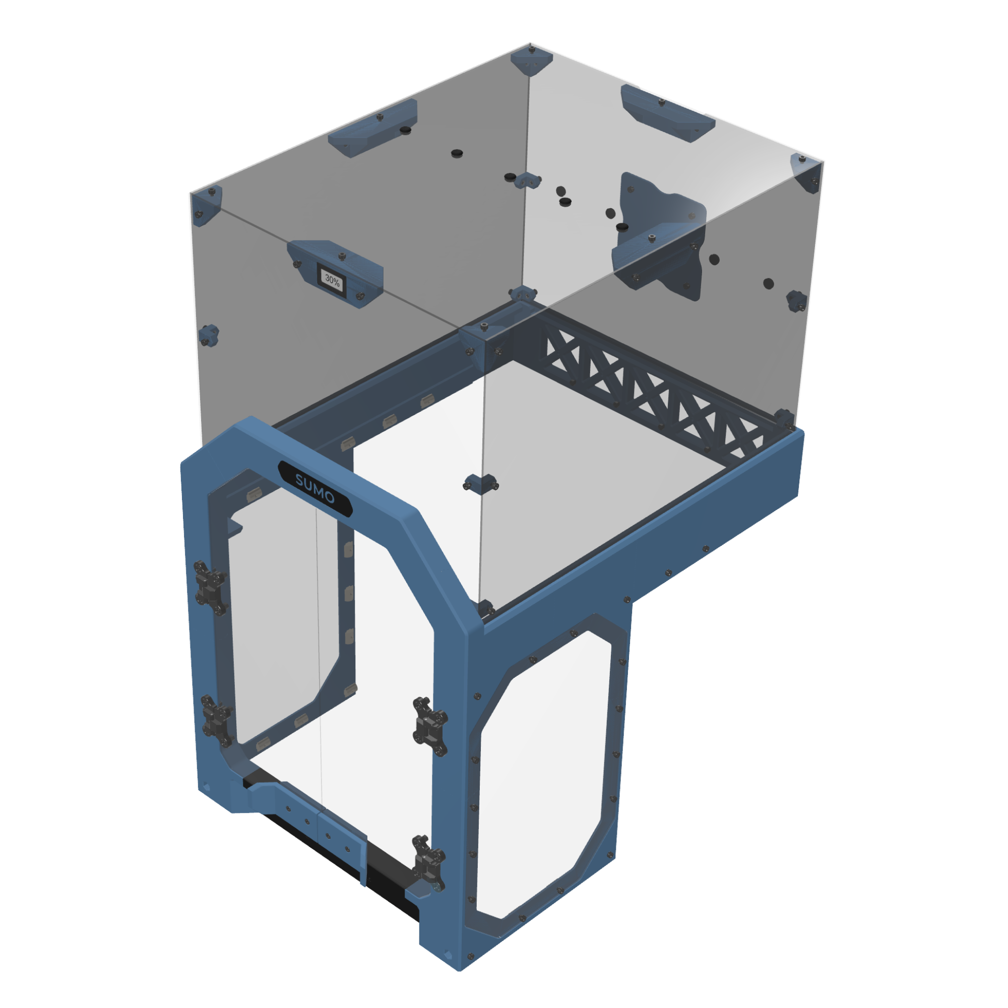
PLEXIGLASS TIP FOR ASSEMBLY
The plexiglass will come covered in a protective film. OUR CURRENT PROTECTIVE FILM IS TRANSPARENT SO THAT WE CAN CHECK FOR DEFECTS IN THE PLEXIGLASS PRIOR TO SHIPPING THE PRODUCT. We recommend removing the film around the corners and around the holes as you assemble, but wait until the enclosure is fully assembled to remove the remainder of the film to avoid unnecessary scratches. Also, be careful with the door frame (especially after attaching the door) because this part that can easily be cracked.
To avoid spending an excess amount of time removing the protective wrapping, pull the wrapping TOWARDS you instead of upwards (counterintuitive but it works). This prevents the protective covering from tearing and allows you to remove the majority of the covering in a single piece.
-
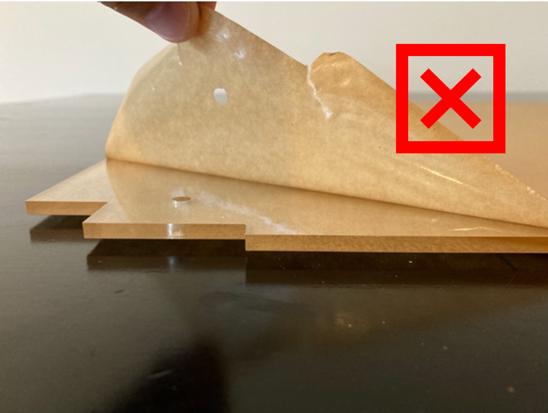
BAD FORM
-
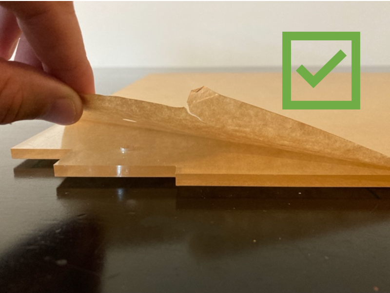
GOOD FORM
-


NUT INSTALL TIP FOR ASSEMBLY
Some of the steps will involve adding press-fit nuts into the parts. If you are having trouble getting the nuts to fully seat into the part, try this tip where you use a bolt to pull the nut into the correct location.
-
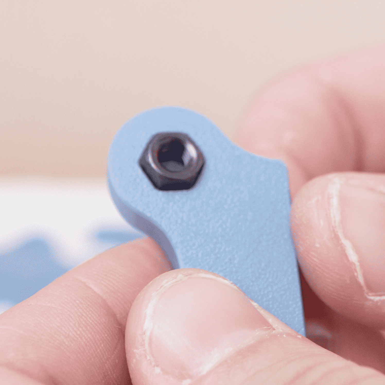
STEP 1
Grab a spare bolt and loosely place the nut in place
-
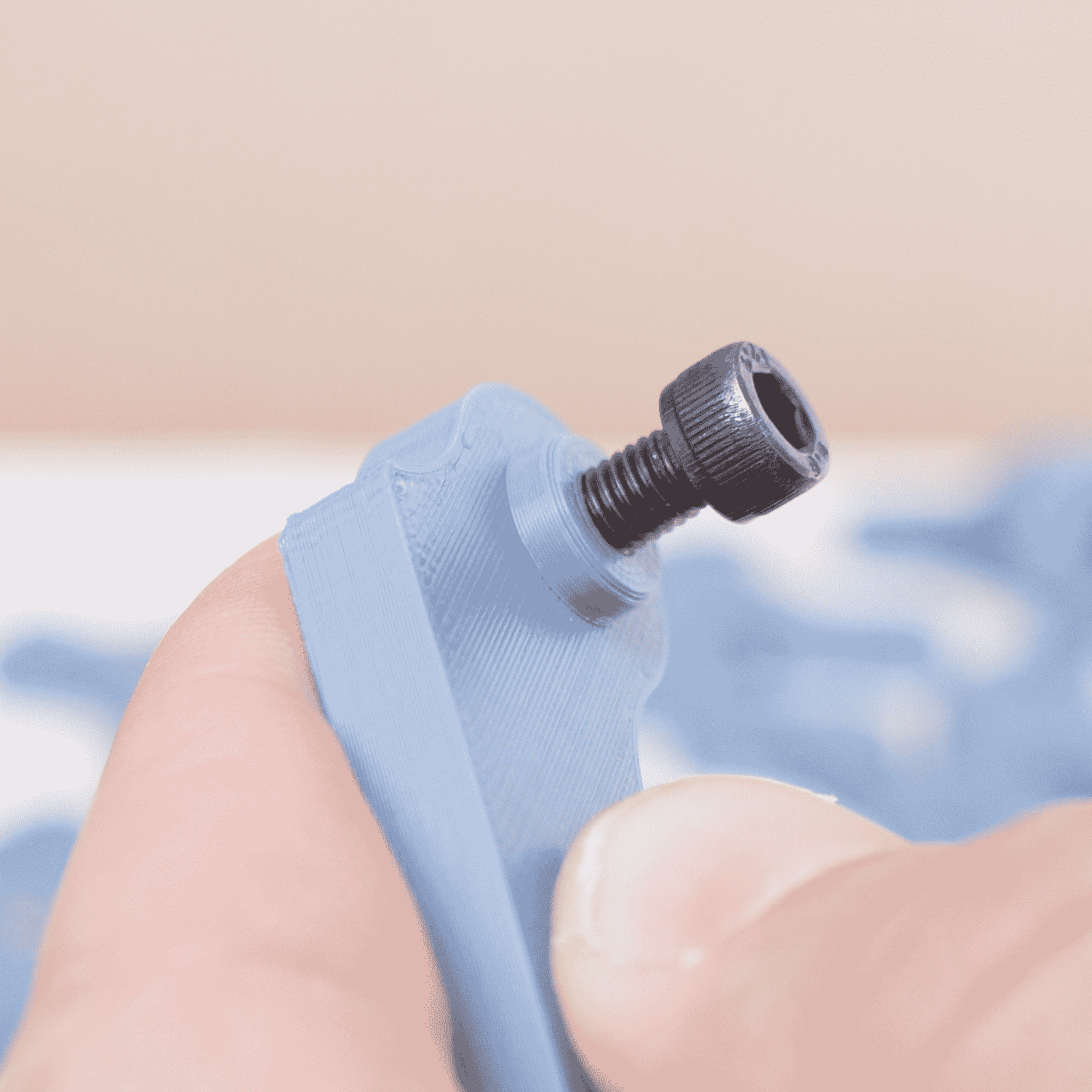
STEP 2
Add the bolt to the hole and thread into the nut
-
STEP 3
Using an Allen wrench, tighten the bolt until it becomes snug
-
STEP 4
The nut should be pulled into place by the bolt from the opposite site
-
STEP 5
Remove the bolt from the piece and repeat if needed for other nuts


SUMO ENCLOSURE PRINTS
The SUMO Enclosure is made up of 9 sets of prints (8 if you have an XL with the antenna on the side instead of the rear). If you print the 9 print sets, you will be able to assemble the entire enclosure. We have created a Standard Build Print List of all required parts for the SUMO Enclosure.
For the Upper Chamber, there are a lot of different accessory parts that you can print - these prints can be found by reviewing the different part options below.
Collapsible content
SUMO PRINT LIST
SUMO Build Print List
|
Print #
|
File
|
Quantity
|
Required?
|
Variations?
|
| 1 | COAXIAL SIZER | 1 | YES | NO |
| 1 | LEFT FRONT BOTTOM | 1 | YES | NO |
| 1 | MAGNET PUSHER | 1 | YES | NO |
|
1
|
RIGHT FRONT BOTTOM
|
1
|
YES
|
NO
|
| 1 | TEMPLATE - BACK | 1 | YES | NO |
| 1 | TEMPLATE - FRONT TOP & BOTTOM | 1 | YES | NO |
| 1 | TEMPLATE - LCD | 1 | YES | NO |
| 1 | TEMPLATE - UNDER SHRAPNEL | 1 | YES | NO |
| 1 | TEMPLATE PEG | 2 | YES | NO |
|
2
|
RIGHT FRONT TOP
|
1
|
YES
|
NO
|
|
2
|
LEFT FRONT TOP
|
1
|
YES
|
NO
|
| 2 | DOOR KNOB BACK LEFT | 1 | YES | NO |
| 2 | DOOR KNOB BACK LEFT | 1 | YES | NO |
| 2 | DOOR KNOB FRONT PLAIN LEFT | 1 | YES | YES |
| 2 | DOOR KNOB FRONT PLAIN RIGHT | 1 | YES | YES |
| 2 | DOOR KNOB FRONT WITH SUMO LEFT | 1 | YES | YES |
| 2 | DOOR KNOB FRONT WITH SUMO RIGHT | 1 | YES | YES |
|
3
|
FRONT CROSSBEAM
|
1
|
YES
|
NO
|
|
4
|
SUMO NAMEPLATE
|
1
|
YES
|
CUSTOMIZABLE
|
|
5
|
LEFT FRAME BOTTOM | 1 |
YES
|
NO
|
| 5 | LEFT FRAME TOP | 1 | YES | NO |
|
5
|
RIGHT FRAME BOTTOM |
1
|
YES
|
NO
|
| 5 | RIGHT FRAME TOP | 1 | YES | NO |
| 6 HEX | RIGHT HEX BACK | 1 | YES | SIDE OR REAR ANTENNA |
| 6 HEX |
LEFT HEX BACK | 1 | YES | SIDE OR REAR ANTENNA |
| 6 HEX | MIDDLE HEX BACK | 1 | YES | SIDE OR REAR ANTENNA |
| 6 SOLID | RIGHT SOLID BACK | 1 | YES | SIDE OR REAR ANTENNA |
| 6 SOLID | LEFT SOLID BACK | 1 | YES | SIDE OR REAR ANTENNA |
| 6 | HEX NUT | 5 | YES | NO |
| 7 | CORNER GUARD RIBBED | 4 | NO | PLAIN OR RIBBED |
| 7 | FAN HOLE COVER | 1 | NO | YES - MULTIPLE |
| 7 | NUT SPACER | 4 | YES | NO |
| 7 | SIDE CORNER | 8 | YES | NO |
| 7 | TOP CORNER | 4 | YES | YES - MULTIPLE |
| 7 | TOP CORNER GUARD | 4 | NO | YES |
| 7 | TOP MIDDLE SUPPORT | 3 | YES | YES |
| 7 | TOP MIDDLE SUPPORT WITH HYGROMETER | 1 | YES | YES |
| 8 | FILAMENT HOLDER OFFSET | 1 | YES | NO |
| 8 | HEX LOCK | 2 | YES | NO |
|
8
|
LCD PLATE
|
1
|
YES
|
NO
|
| 8 | LEFT HINGE SET | 2 | YES | NO |
| 8 | OVOID LOCK | 2 | YES | NO |
| 8 | RIGHT HINGE SET | 2 | YES | NO |
| 8 | HINGE BACK | 4 | YES | NO |
|
9 (REAR ANTENNA ONLY) |
ANTENNA EXTENSION | 1 | YES | YES (8MM OR 11MM) |
ALT PRINT WITH BELT BOLT ACCESS
Due to multiple requests, we've created an alternate FRONT TOP print that provides access to the bolt used to tighten the belts on the Prusa XL.
If you would like this front panel, please print the SUMO Print 2 - ALT & SUMO Print 8 Accent - ALT (which has the covers for the slots).
Our Prusa XL at the office has not required belt tightening, so this is completely optional and was only created due to requests from customers.
SUMO UPPER CHAMBER PART OPTIONS (PRINT 7)
The Upper Chamber of the SUMO has a lot of customizable options for modifying the SUMO to suit your needs.
The Upper Chamber parts can be found within Print 7.
Collapsible content
Print 7 - TOP CORNER SELECTION
Top Corner Selection
The standard TOP CORNER part is what we recommend that most people print for the SUMO Enclosure.

If you are planning to add internal wiring or something like the TP-LINK TAPO or WYZE CAM V3 to your SUMO Enclosure, we recommend printing a TOP CORNER WITH CABLE CHANNEL for better cable management.

The mounts for the WYZE CAM, TAPO, and GOPRO can be found on the SUMO ACCESSORY PRINTS Page.
Print 7 - TOP MIDDLE SUPPORT SELECTION
Top Middle Support Selection


Print 7 - FAN COVER SELECTION
Fan Hole Cover Selection
If you DO NOT plan on adding a fan to your enclosure, consider printing a FAN HOLE COVER for the SUMO. For the bolts to fit correctly with the FAN HOLE COVER, you will need to print x4 NUT SPACER prints - these are included in the print set.

If you DO want to add a fan to your 3D printer enclosure, you SHOULD NOT print the Fan Hole Cover. Please choose from the options below:
Option #1: 120mm Fan
You can add a 120mm Noctua Fan without any additional prints; use the screws included in the kit to attach it to the SUMO.
CLICK HERE TO VIEW THE 120MM FAN ASSEMBLY GUIDE

Option #2: 120mm Fan with HEPA Filter
If you would like to add an air filter to your fan setup, use the link below for more details on the HEPA Filter print.
CLICK HERE TO VIEW THE HEPA FILTER ASSEMBLY GUIDE

Option #3: 120mm Fan with Air Duct Attachment
To add a duct to the SUMO enclosure, print the Air Duct Attachment by following the link below.
CLICK HERE TO VIEW THE 4-INCH AIR DUCT MOUNT ASSEMBLY GUIDE

Option #4: 120mm Fan with HEPA Filter + Air Duct Attachment
For a print set containing a HEPA Filter and an Air Duct Attachment, follow this link.
CLICK HERE TO VIEW THE HEPA + DUCT ASSEMBLY GUIDE

Print 7 - CORNER COVER SELECTION
Corner Cover Selection
While the corner covers are not required for the SUMO enclosure to be functional, we STRONGLY recommend that you use them. There are two options of corner covers to choose from - a version with ribs and a plain version.
Corner Cover with Ribs

Corner Cover Plain

Modular Top Corner
If you're looking to add some additional functionality to the corner of your printer, consider adding this Modular Top Corner Accessory Print to your setup.
CLICK HERE FOR THE MODULAR TOP CORNER ASSEMBLY GUIDE

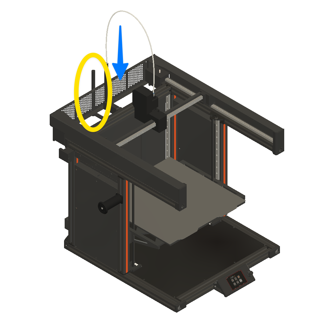
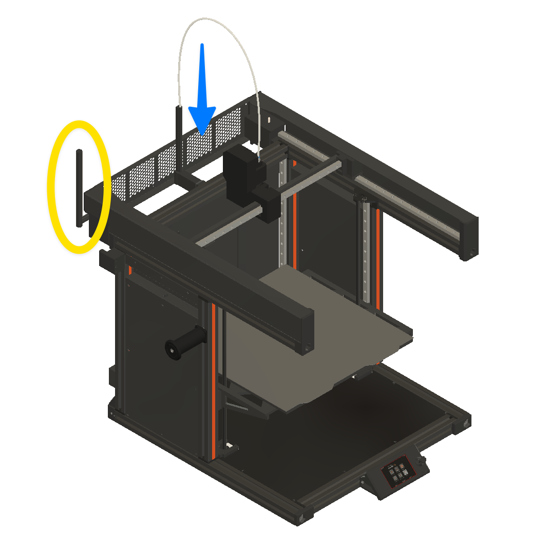
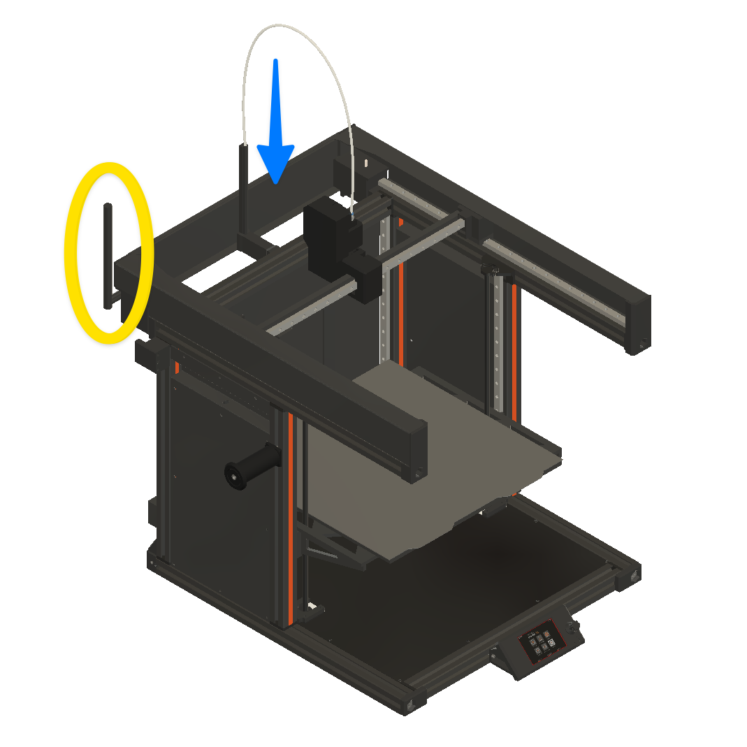
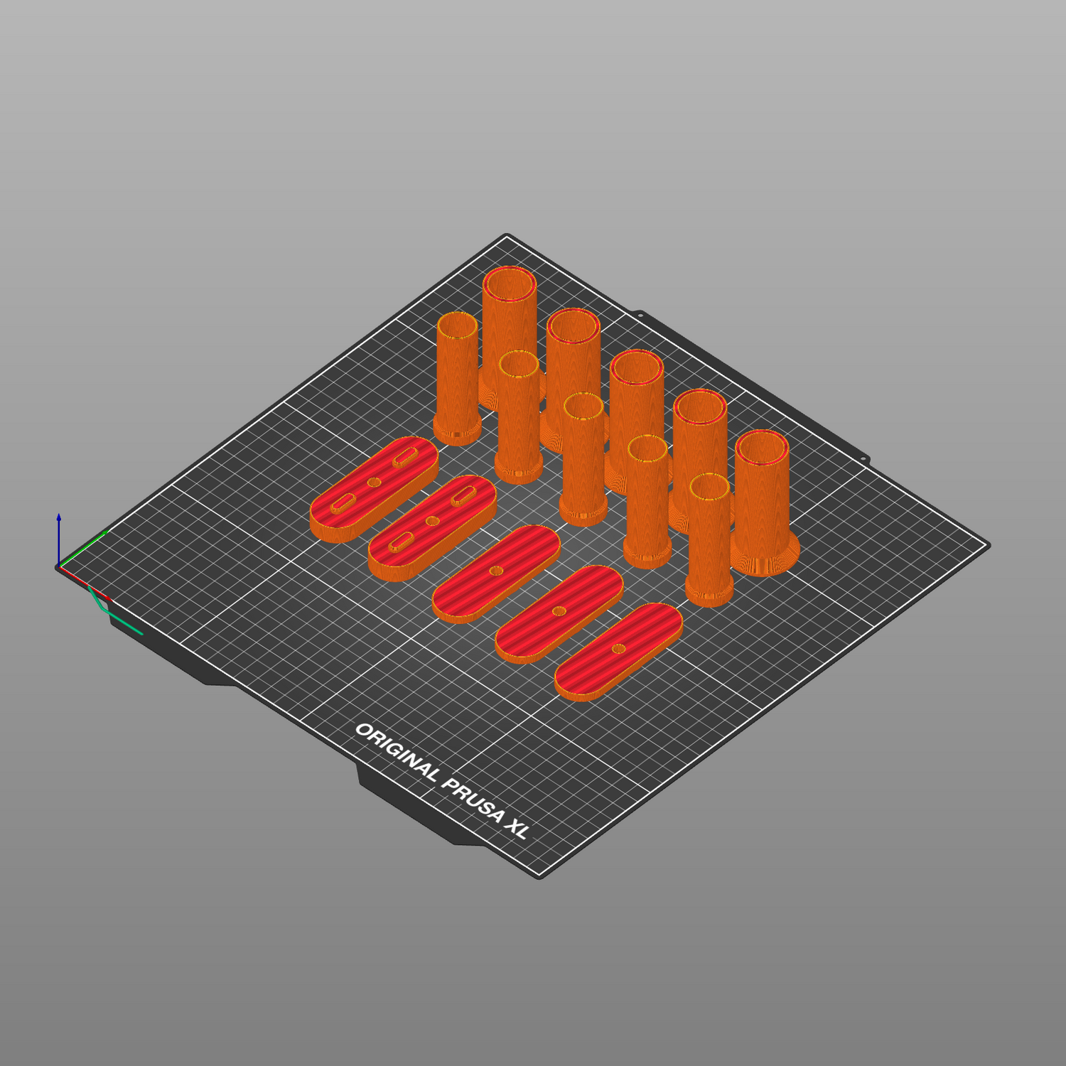
REAR ANTENNA FILES (PRINT 9)
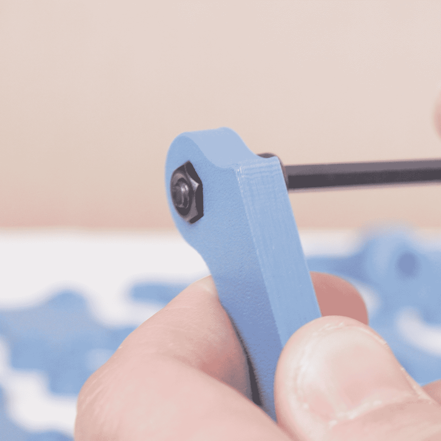
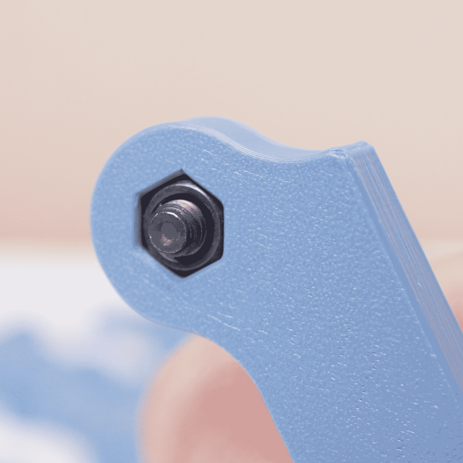
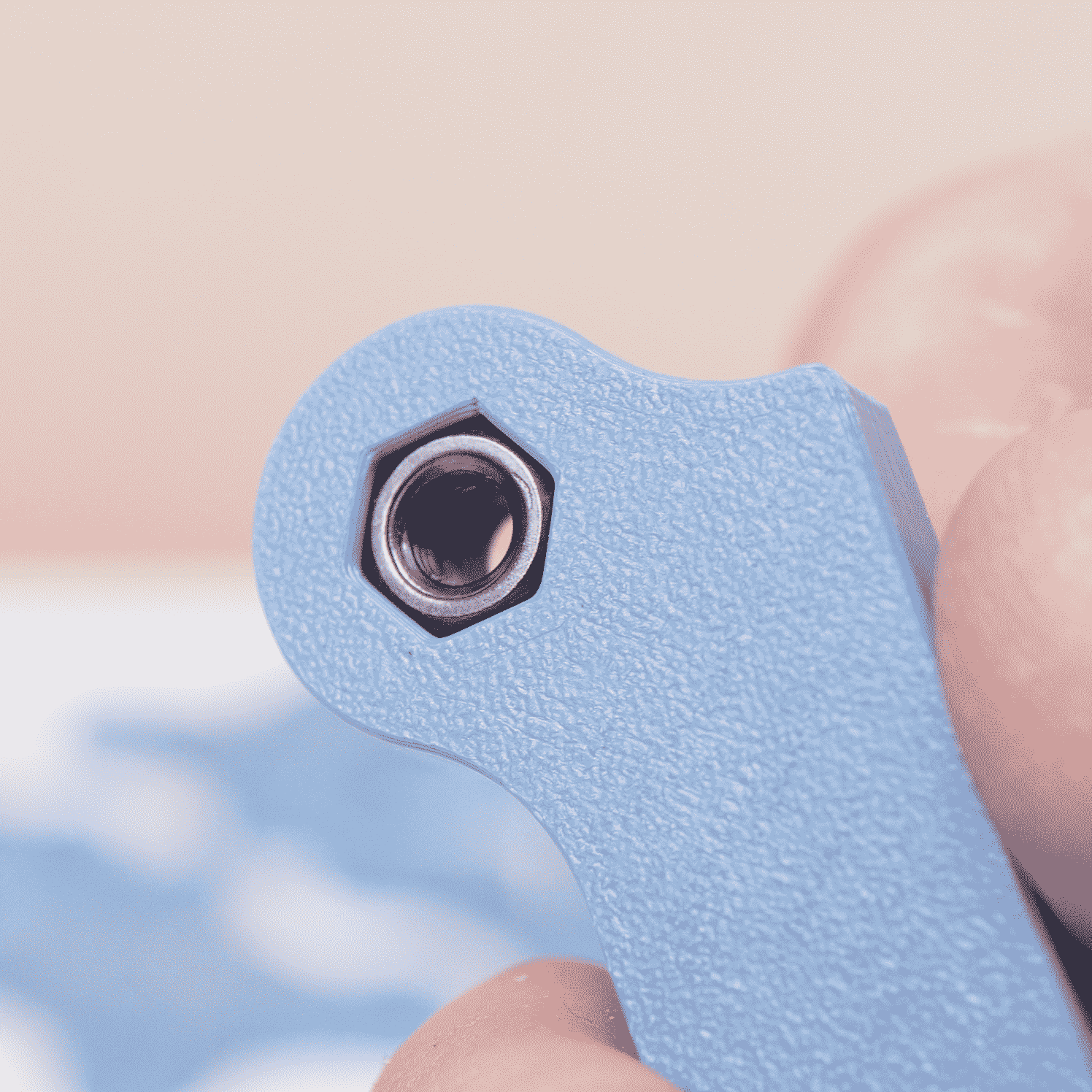
Prusa has shipped the Prusa XL with multiple coaxial antenna sizes.
Please select the proper size antenna print for those of you with a Prusa XL with a rear antenna.
If the antenna is located on the side of your Prusa XL, you do not need to print any adapters for the antenna.
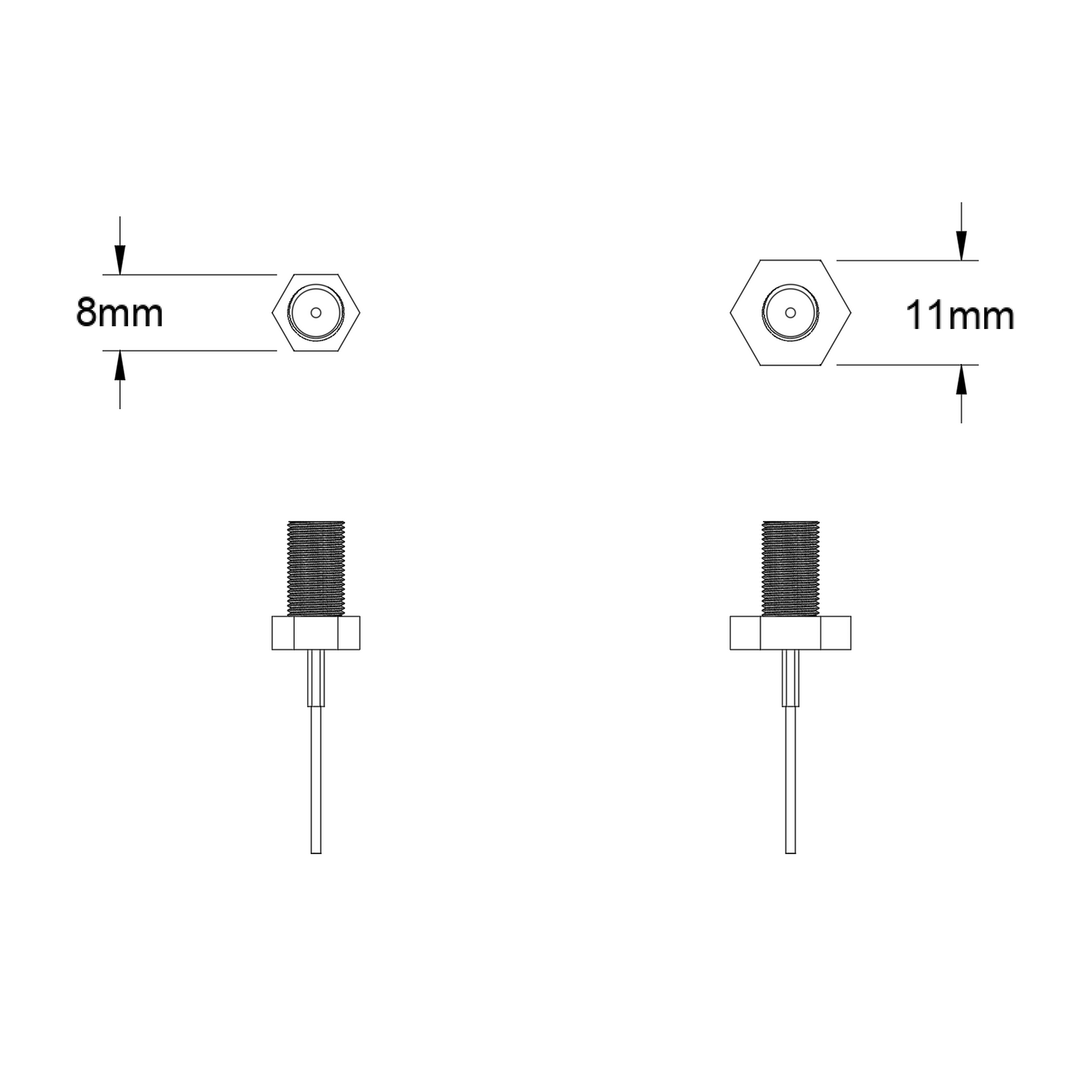
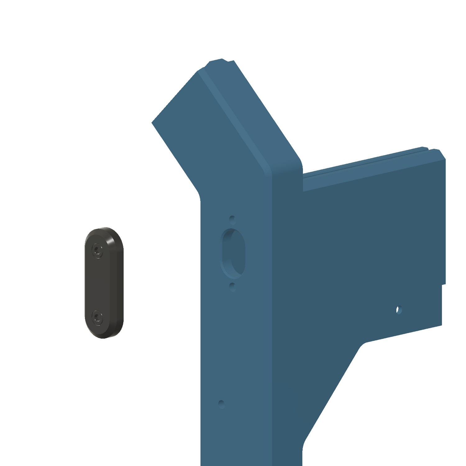
REAR COAXIAL EXTENSION
8MM OR 11MM ANTENNA
Use the figure to the right to determine which adapter to print. Alternatively, SUMO Print 1 includes a small print for assessing the antenna size.
CUSTOMIZE YOUR SUMO
SUMO ACCESSORY PRINTS
Make your SUMO into a setup that works for your workflow with our accessory prints!
EXTRA BOLTS FOR SPOOL HOLDERS
PRINT MORE SPOOL HOLDERS
Included in the SUMO kit are some extra bolts for adding up to 6 filament spool holders to your Prusa XL - the extra spool holder files are included in our downloadable files.