
INTRODUCTION
Thank you for your purchase of the Universal 3D Printer Enclosure!
We have made this Assembly Guide as detailed as possible so that the build goes smoothly. We have recently transitioned the guide from PDF format to an online version so that everyone will have access to the most updated version of the guide.
FAQ
What print settings should I use?
We recommend printing the parts at 15% infill at 0.20 mm layer height.
How much filament does the enclosure build require?
Approximately 85% of a single 1KG roll will be used if you have no print failures with the print settings listed above.
What type of filament should I use for the printable parts?
We recommend printing get enclosure in PLA or PETG.
How long will the prints take?
With a Prusa MK3/MK3S printing at 0.20 mm layer height with the “Quality” settings selected, the prints take a total of 65 hours. Can you get everything printed before Amazon delivers the kit?
Do I need to do anything differently if I am planning to create a Daisy-Chain (DC) enclosure?
If you have purchased two enclosures and plan to do the Daisy-Chain (DC) build, you will need to print one Standard Build.
You DO NOT need to print two Standard Builds - there are special DC prints available to complete the rest of the DC build. Please refer to the Daisy-Chain section for more details.
What color should I print the parts for my enclosure?
Prusa Orange or Galaxy Black? Or all white? Multicolored? Be sure to share your build with us on social media!
BILL OF MATERIALS
Review Bill of Materials (BOM)
BOM of Universal 3D Printer Enclosure
***You WILL NOT use all of the included fasteners. We have included extras for future accessories and for you to customize your enclosure as needed.***
***Screws are included for mounting the PSU to a LACK table or for stacking 2 LACK tables using the LACK STACK Print Set (see our ACCESSORY PRINTS for more details on the LACK STACK).***
WARNING
DO NOT OVERTIGHTEN!!!
We’ve included tools for tightening the parts but tightening by hand will be sufficient in most cases. The nuts should be snug; however, overtightening may cause the plexiglass to crack.
***The one exception to this is the door hinges! To have the door swing properly, you will need to tighten it snugly, or the door will hit the frame.***
TIPS FOR ASSEMBLY
The plexiglass will come covered in a protective film. We recommend removing the film around the corners and around the holes as you assemble but wait until the enclosure is fully assembled to remove the remainder of the film to avoid unnecessary scratches. Also, be careful with the door frame especially after attaching the door as this is the part that can most easily be cracked.
To avoid spending an excess amount of time removing the protective wrapping, pull the wrapping TOWARDS you instead of upwards (counterintuitive but it works). This prevents the protective covering from tearing and allows you to remove the majority of the covering in a single piece.
-
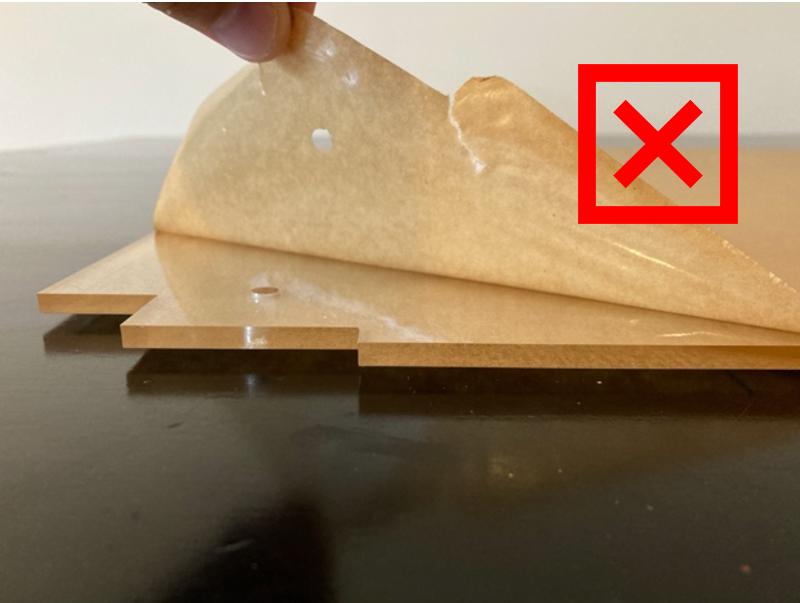
BAD FORM
-
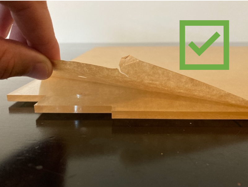
GOOD FORM
-


0 - GETTING STARTED
Before we begin with the enclosure assembly, some printers require small modifications in order to function correctly inside of the Universal 3D Printer Enclosure. Feel free to skip this section if you have a printer that is different from the ones listed below.
Printer Modifications
Prusa MK2/MK3 Modifications
Head Bed Cable Cover (REQUIRED)
0 - GETTING STARTED -> PRUSA PRINTER MODIFICATIONS -> [PRINTER TYPE] -> PSU WIRE GUIDE REPLACEMENT
Please replace the heat bed cable cover with a new PSU Wire Guide Replacement part set to reduce the stress on the heat bed cable. If you are upgrading from a LACK enclosure, you may have already completed this step. All files were taken from the websites listed below; please refer to the links as needed for assembly.
60 Degree PSU Cover for MK3/MK3S
30 Degree PSU Cover for MK2/MK2S
POWER SUPPLY UNIT (PSU) Relocation (OPTIONAL)
0 - GETTING STARTED -> PRUSA PRINTER MODIFICATIONS -> [PRINTER TYPE] -> PSU BRACE REPLACEMENT
If you would like to relocate your PSU to a location outside of the enclosure, you will need to print a PSU Brace Replacement part to maintain the printer's rigidity. All files were sourced from the links below.
***While it is generally recommended by Prusa to remove the PSU from the enclosure due to the heat exposure on the electronics, we have never had an issue with any of our printers after having the PSU inside of the Universal Enclosure for over 5 years.***
MK3 PSU Mounting Options
For mounting the PSU to the LACK using the included extra fasteners, please follow the link below to the PSU Mount for Lack accessory part set.
PSU Mount for Lack
If you would rather add a base to your PSU so it can stand freely, we have a Prusa MK3 Silver PSU Base part available for the original silver PSU for the MK3.
PRUSA MK3 Silver PSU Base
Creality Ender 3 Modifications
If you would like to remove the Ender 3 PSU from the enclosure, we have an Ender 3 PSU Base accessory part available so that the PSU can stand freely.
Ender 3 PSU Base
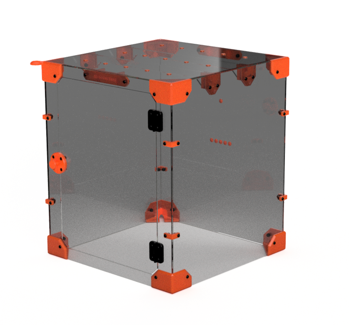
1 - STANDARD BUILD
To streamline the STL selection process, we created a Standard Build of the Universal Enclosure. Think of this as the "default" build for anyone who wants to get the enclosure built.
We recommend that most people start with this build - you can always make adjustments to your enclosure once you have it assembled.
We will also discuss alternative part options to the Standard Build to help you decide if you want to use any of the variations with your enclosure.
STANDARD BUILD PRINTS
1 - STANDARD BUILD -> 1 - STANDARD BUILD PRINTS 1-4 -> [print files]
The Standard Build consists of 4 sets of prints. If you print the 4 print sets, you will be able to assemble the entire enclosure. We have created a Standard Build Print List of all of the required parts for a Standard Build of the enclosure.
The Print # corresponds to what print set each part is located in so that you can easily find the part in the folder in case you have a print failure or want to exchange a part for one of the variations available.
Collapsible content
STANDARD BUILD PRINT LIST
Standard Build Print List
|
Print #
|
File
|
Quantity
|
Required?
|
Variations?
|
|
1
|
Doorknob set
|
1
|
Yes
|
No
|
|
1
|
Filament Hole Plug
|
0 to 21
|
No
|
No
|
|
1
|
Side Corner Support
|
8
|
Yes
|
No
|
|
1
|
Top Middle Support
|
2
|
Yes
|
Yes
|
|
2
|
Solid Feet
|
3
|
Yes
|
Yes
|
|
2
|
Channel Feet
|
1
|
Yes
|
No
|
|
2
|
Channel Plug Arch
|
1
|
Yes
|
Yes
|
|
3
|
Top Corner set
|
4
|
Yes
|
Yes
|
|
4
|
Cross Support
|
4
|
Yes
|
Yes
|
|
4
|
Top Corner Support
|
4
|
Yes
|
No
|
|
***For the products with variations, you can mix and match as long as you end up with the correct quantity. For example, you can print 2 Solid Feet and 2 Channel Feet for a total of 4 Feet.***
|
||||
STANDARD BUILD PART OPTIONS
Collapsible content
FOOT SELECTION
Foot Selection
You will need 4 feet for the build. Below are the various options and recommendations based on your setup. The Standard Build Set includes 3 SOLID FOOT prints and 1 CHANNEL FOOT print.

YOU WILL NEED TO PRINT AT LEAST 1 CHANNEL FOOT. This design allows you to remove the power supply from the enclosure without needing to remove the wires from your printer as well as run your power cord outside of the enclosure if you leave the PSU inside of the enclosure. The Standard Build Set includes 1 CHANNEL FOOT. Various inserts are also available including a SOLID INSERT if you just want to plug the hole, a HOLE INSERT for the PSU cable (for PRUSA MK3) or the CHANNEL INSERT for running the PSU cable outside of the enclosure.

TOP CORNER SELECTION
Top Corner Selection
As with the feet, you will need 4 TOP CORNER pieces per enclosure. You will also need to print 4 TOP SUPPORTS that support the top plexiglass. The Standard Build Set includes 3 SOLID TOP CORNER prints and 1 HOLE TOP CORNER print with a TOOL INSERT. The standard SOLID TOP CORNER is made for the top corners where you do not need to hold tools, run wires, or add additional ventilation to your enclosure.

The CHANNEL TOP CORNER is made where you can run wires or add various inserts for different needs. Feel free to design your own insert with the included STEP file (SOLID INSERT.STEP)!

The CHANNEL TOP CORNER is useful you need to pass a cable outside of the enclosure (CHANNEL INSERT) or to hold a tool (TOP INSERT TOOL HOLDER). The hole can also be used as a vent to control the temperature as needed and plugged with the TOP INSERT SOLID.

There are 2 versions of the TOP SUPPORT:
TOP SUPPORT SLIDE – this allows you to easily “slide” the piece into place which enables you to easily run new wires into your enclosure whenever you decide you would like to do so. Make sure the orientation of the hex nut is correct when sliding!
TOP SUPPORT HEX – this version is fixed into place with a through bolt. There will be slightly improved stability with this version, but the ability to easily add a wire to your enclosure will be lost.
We recommend using the TOP SUPPORT SLIDE in most situations as the stability is sufficient for most applications. 4 TOP SUPPORT SLIDES are included in the STANDARD BUILD.

TOP MIDDLE SUPPORT SELECTION
Top Middle Support Selection
There are 2 variants of the TOP MIDDLE SUPPORT (SOLID or HYDROMETER). The compatible hydrometer is included in the kit. The Standard Build Set has 2 TOP MIDDLE SUPPORT prints (one of each version).

CROSS SUPPORTS SELECTION - IMPORTANT FOR CONCRETE PAVERS UNDER THE PRINTER
Cross Supports Selection
There are 2 versions of the CROSS SUPPORT available, one with and one without holes. We recommend using the one WITHOUT holes because this allows you to easily remove the CROSS MEMBER plexiglass in order to access your printer. If you would rather have an extremely rigid enclosure, the CROSS SUPPORT WITH HOLES will increase rigidity but accessing the printer will be more difficult.

If you intend to use your enclosure with a Prusa MK3/MK3S with a CONCRETE PAVER as well as the standard filament holder that attaches to the printer (with filament rolls inside the enclosure), then you will need to print 2 CROSS SUPPORT ANGLE pieces in exchange for 2 CROSS SUPPORT pieces (so 2 CROSS SUPPORT ANGLE + 2 CROSS SUPPORT). These are intended to provide clearance between the ceiling and filament rolls if you have the paver positioned beneath the printer. If you do not use a paver, you will have plenty of extra space with the standard CROSS SUPPORTS.

STANDARD BUILD ASSEMBLY
Collapsible content
STANDARD BUILD EXPLODED VIEW
Standard Build Exploded View

FRONT ASSEMBLY
Door Knob Assembly

Door & Hinge Assembly
The exploded view shown is designed for the door to swing towards the right if you are facing the enclosure. If you would like the door to swing towards the left, simply add the two hinges, Door Knob, and Top Support to the opposite side of the Front plexiglass.


BACK ASSEMBLY
Back Assembly
SIDE ASSEMBLY
Side Corner Assembly

Side Panel Assembly


Pro Tip for Reaching the Last Nuts
When you begin assembling the walls, the last nuts can be tricky to reach. We recommend assembling the enclosure on the table where you intend to leave the enclosure as it is somewhat difficult to move around due to the size. When you get to the final few nuts (especially on the last set of feet), position the corner of the enclosure where it hangs slightly off the edge of the table in order to reach the nuts as shown below.

TOP ASSEMBLY
Top Panel Assembly

Top Support Assembly
The TOP SUPPORT pieces will be slid into place in order to support the top plexiglass. The NUT ORIENTATION is important for a proper fit (see below). Additionally, the washer should be on the inside of the plexiglass. Having sliding TOP SUPPORTS allows for easily running cords in and out if your setup changes.

Cross Member Assembly


FINAL ASSEMBLY
Final Assembly
Congratulations on a job well done! Feel free to customize and add some of the accessory prints included towards the end of this guide! Happy printing!

EXPAND YOUR UNIVERSAL ENCLOSURE
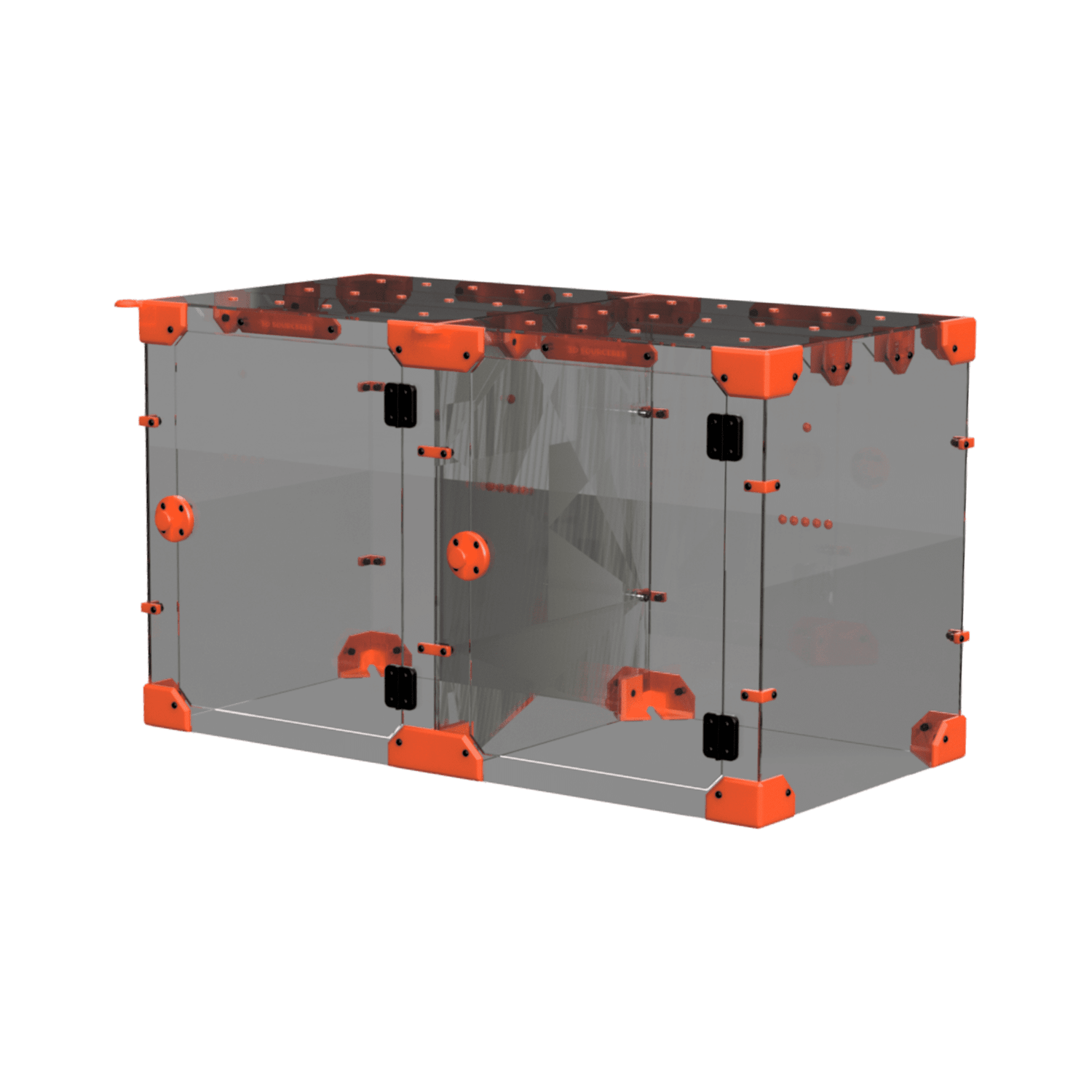
DAISY-CHAIN (DC) EXPANSION
Are you ready to add another enclosure to your setup? Follow this Assembly Guide for the Daisy-Chain Expansion.
MAKE IT YOUR OWN
UNIVERSAL ENCLOSURE ACCESSORY PRINTS
With a wide range of accessory prints, there's something here for just about any 3D printer setup.