
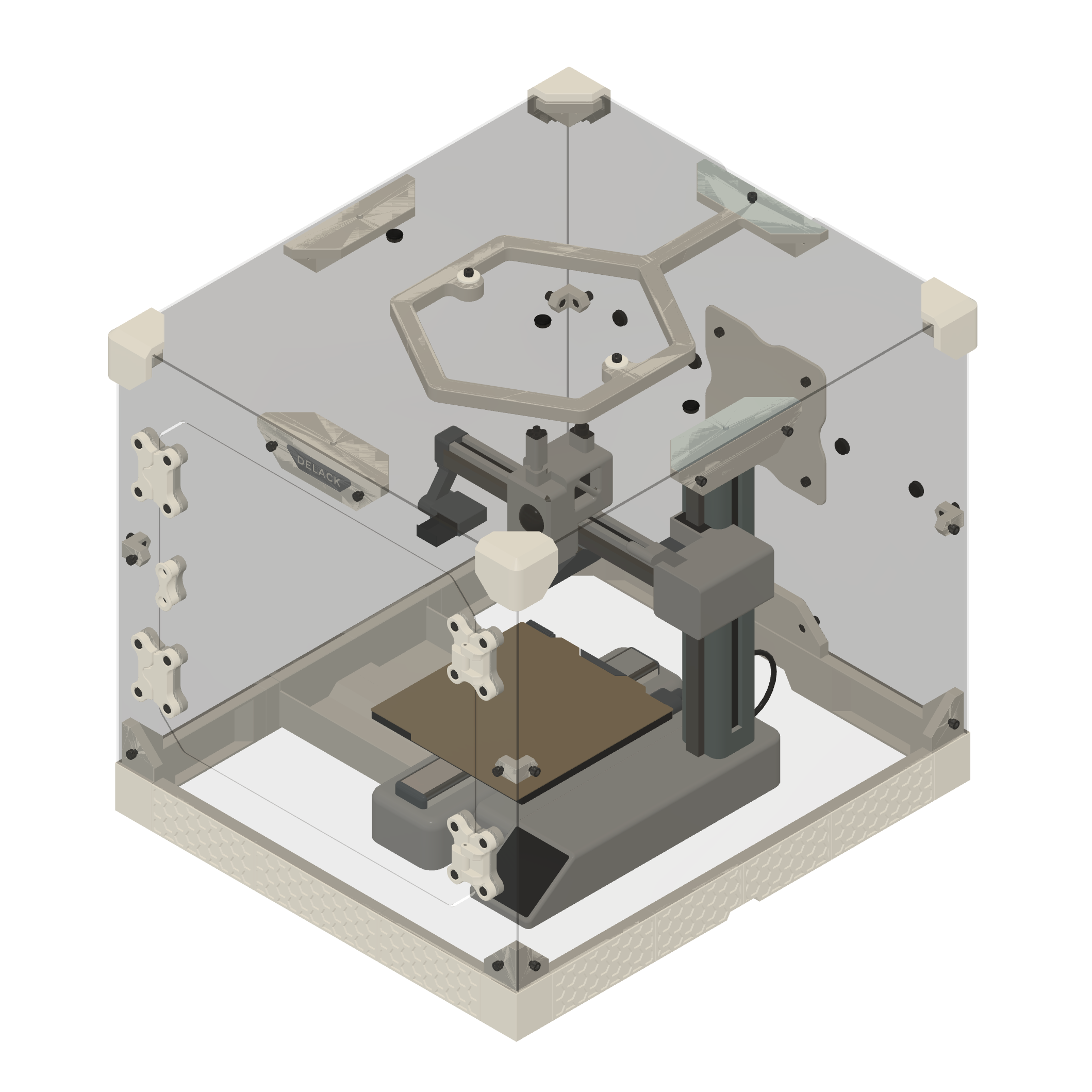
DELACK ENCLOSURE ASSEMBLY GUIDE FOR BAMBU LAB A1 MINI
DOWNLOADS
-
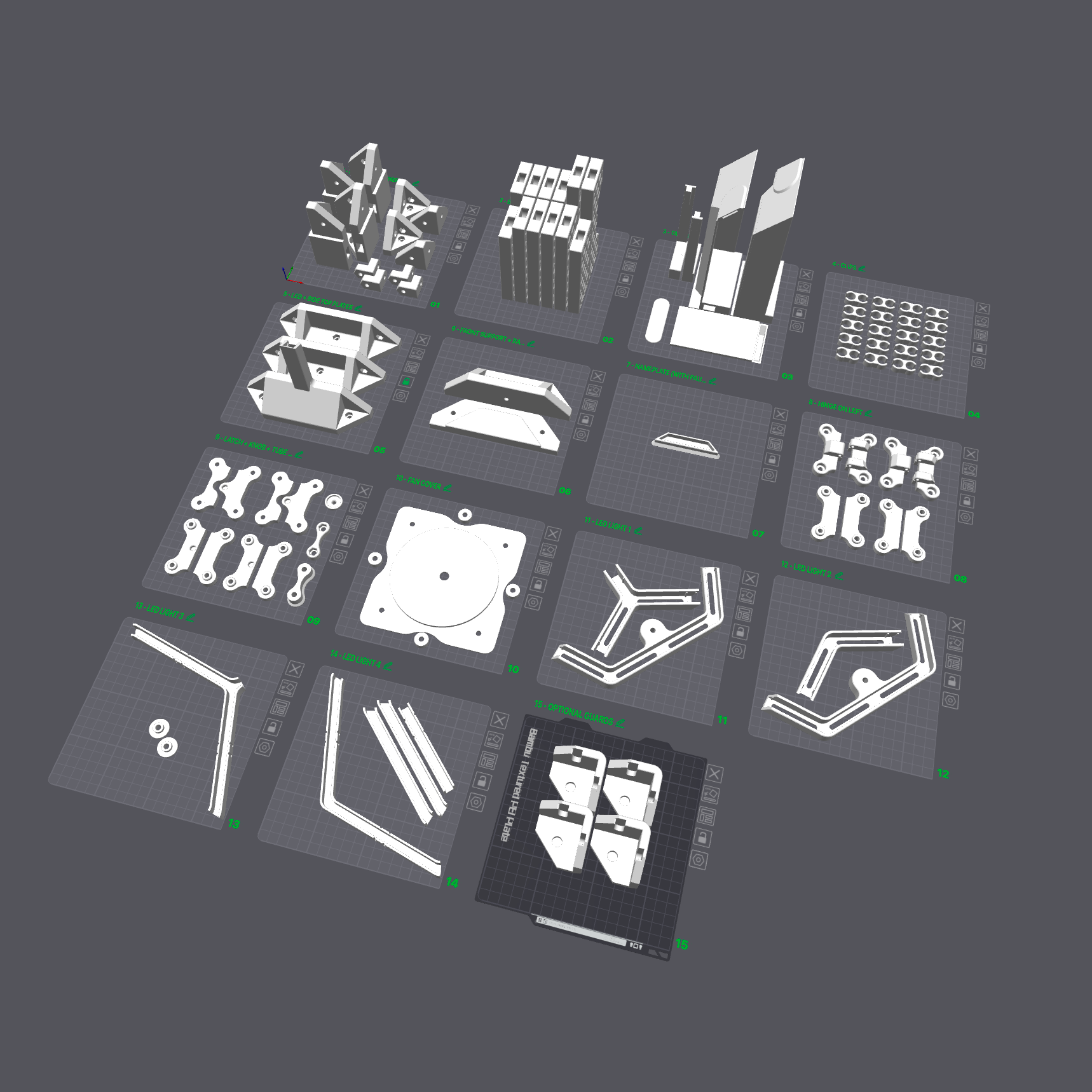
STANDARD BUILD
CLICK TO DOWNLOAD STANDARD FILESx15 prints
Print Profile for DELACK for A1 MINI (no AMS)
-

-
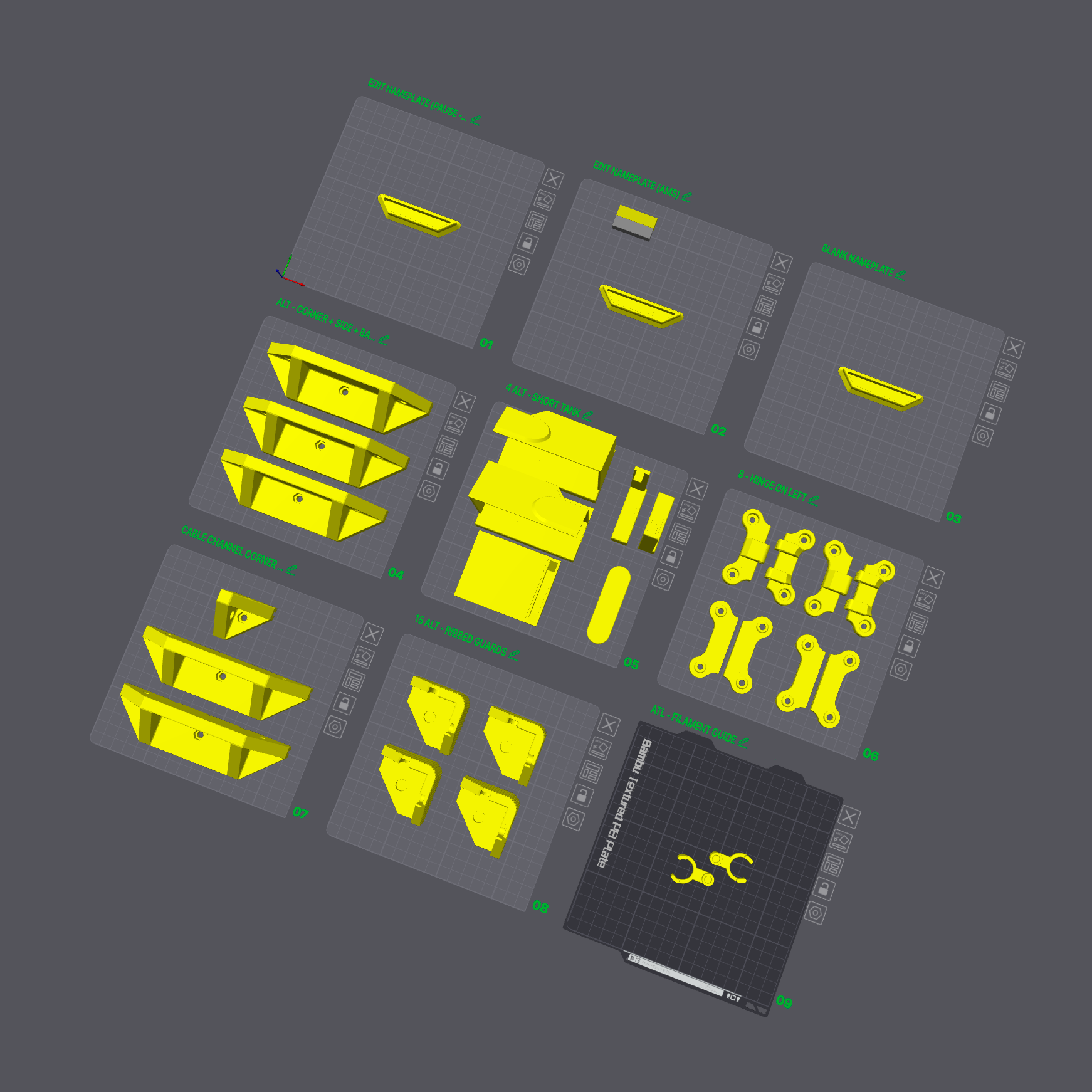
ALT PRINTS
CLICK TO DOWNLOAD ALT FILESx9 prints
Print Profile of alternative prints for DELACK for A1 Mini -


INTRODUCTION
Thank you for your purchase of the DELACK Enclosure for the A1 Mini!
Please select the correct files to print above based on whether or not you have an AMS Lite unit with your A1 Mini.
VIDEO TUTORIAL

FAQ
What print settings should I use?
We recommend using the default 0.2mm layer height settings for printing the DELACK for A1 Mini.
We have profiles available in MakerWorld to make it easy!
How much filament does the enclosure build require?
For the DELACK for A1 Mini, 1.4kg of filament will be used if you print the Standard Build (recommended).
For the DELACK for A1 Mini + AMS Lite, 2.1kg of filament will be used assuming that you print the AMS Stand (which is optional but highly recommended since the AMS needs to be elevated so that the PTFE tubes will be long enough).
What type of filament should I use for the printable parts?
You can print the DELACK in any filament that you prefer (such as Bambu Lab PLA Matte), but we do recommend printing the LED Light parts in a higher-temperature filament such as PETG or ASA if you plan to leave the light on for an extended period of time while printing with higher temperature filament
How long will the prints take?
With a Bambu Lab A1 Mini using the default 0.20mm layer height, the print time is 41 hours.
See if you can getting everything printed before Amazon delivers the kit!
What color should I print the parts for my enclosure?
We printed our example DELACK for A1 Mini enclosure with Bambu Lab Matte Ivory White PLA and Bambu Lab Matte Ash Grey PLA.
Be sure to share the colors you pick with us on MakerWorld and social media!
Why is there a blank USB thumb-drive included?
Back in the day, Prusa printers required users to transfer the gcode from their computer onto thumb-drives and then plug the drive into the 3D printer to start printing. Since some laptops no longer have the USB-A port that Prusa used for the thumb-drive, we decided to provide this USB-A to USB-C thumb-drive as a nice little bonus so that users could avoid the hassle of a dongle - hope you get some use out of it in another way!
BILL OF MATERIALS
Review Bill of Materials (BOM)
BOM of DELACK Enclosure

***You WILL NOT use all of the included fasteners. We have included extras for future accessories and for you to customize your enclosure as needed.***
PLEXIGLASS TIP FOR ASSEMBLY
The plexiglass will come covered in a protective film. OUR CURRENT PROTECTIVE FILM IS TRANSPARENT TO CHECK FOR DEFECTS PRIOR TO SHIPPING. We recommend removing the film around the corners and around the holes as you assemble, but wait until the enclosure is fully assembled to remove the remainder of the film to avoid unnecessary scratches. Also, be careful with the door frame (especially after attaching the door) because this part that can easily be cracked.
To avoid spending an excess amount of time removing the protective wrapping, pull the wrapping TOWARDS you instead of upwards (counterintuitive but it works). This prevents the protective covering from tearing and allows you to remove the majority of the covering in a single piece.
-
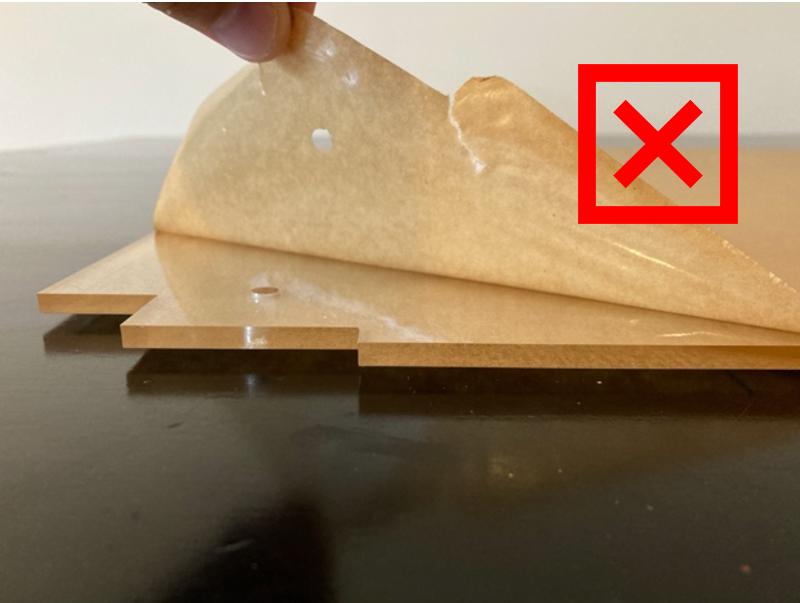
BAD FORM
-
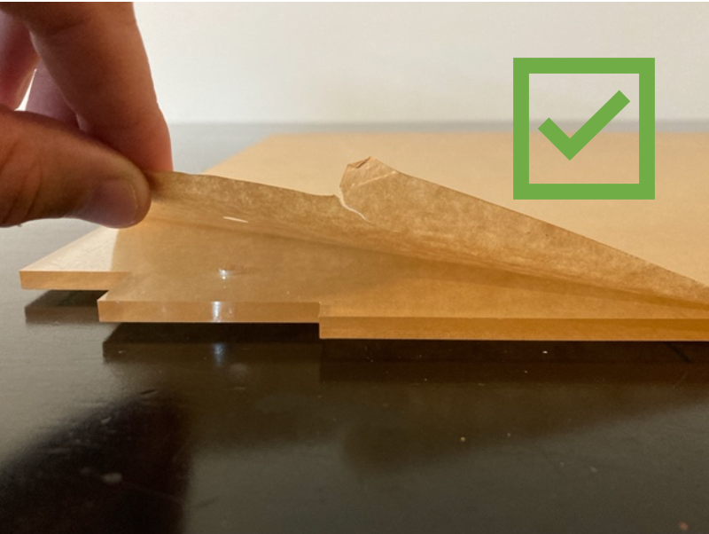
GOOD FORM
-


NUT INSTALL TIP FOR ASSEMBLY
Some of the steps will involve adding press-fit nuts into the parts. If you are having trouble getting the nuts to fully seat into the part, try this tip where you use a bolt to pull the nut into the correct location.
-
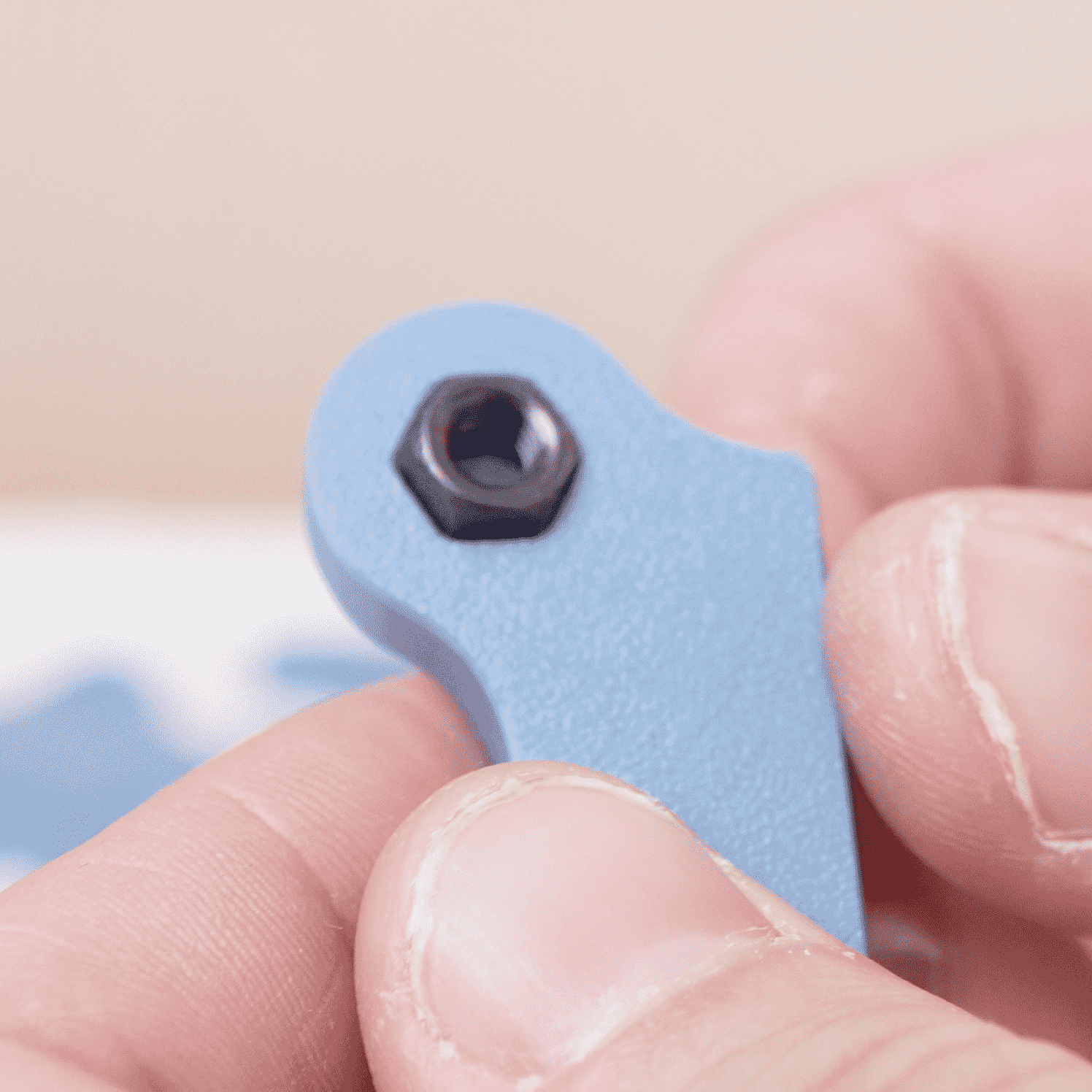
STEP 1
Grab a spare bolt and loosely place the nut in place
-
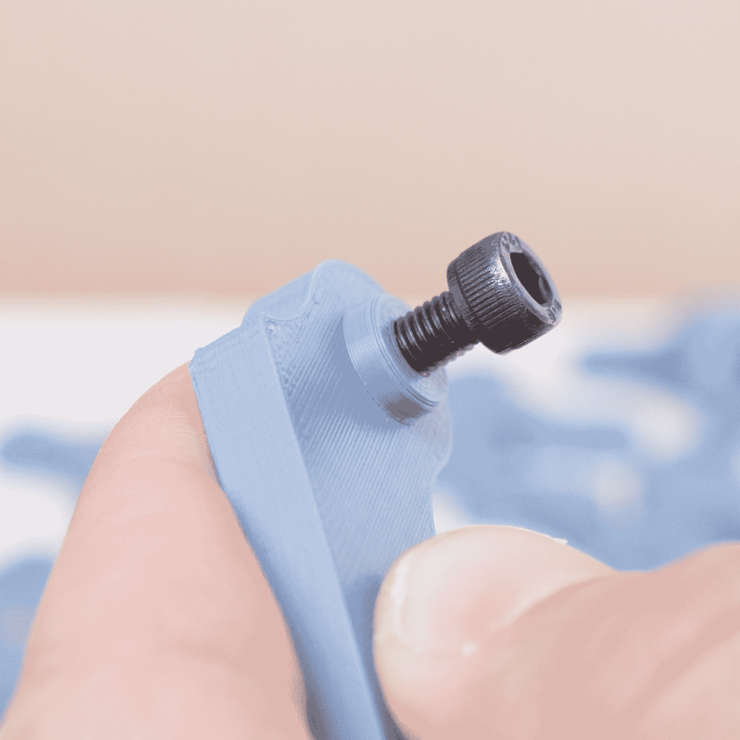
STEP 2
Add the bolt to the hole and thread into the nut
-
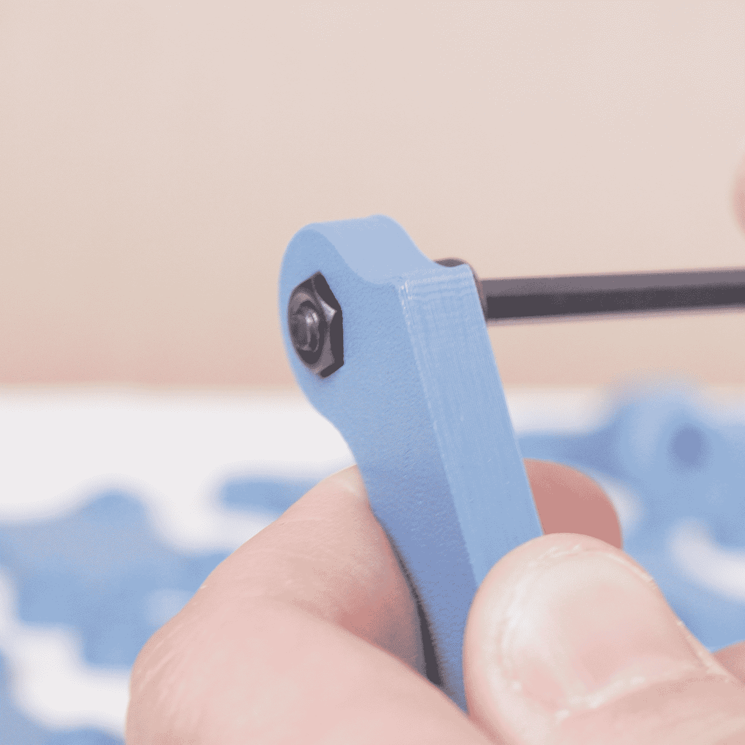
STEP 3
Using an Allen wrench, tighten the bolt until it becomes snug
-
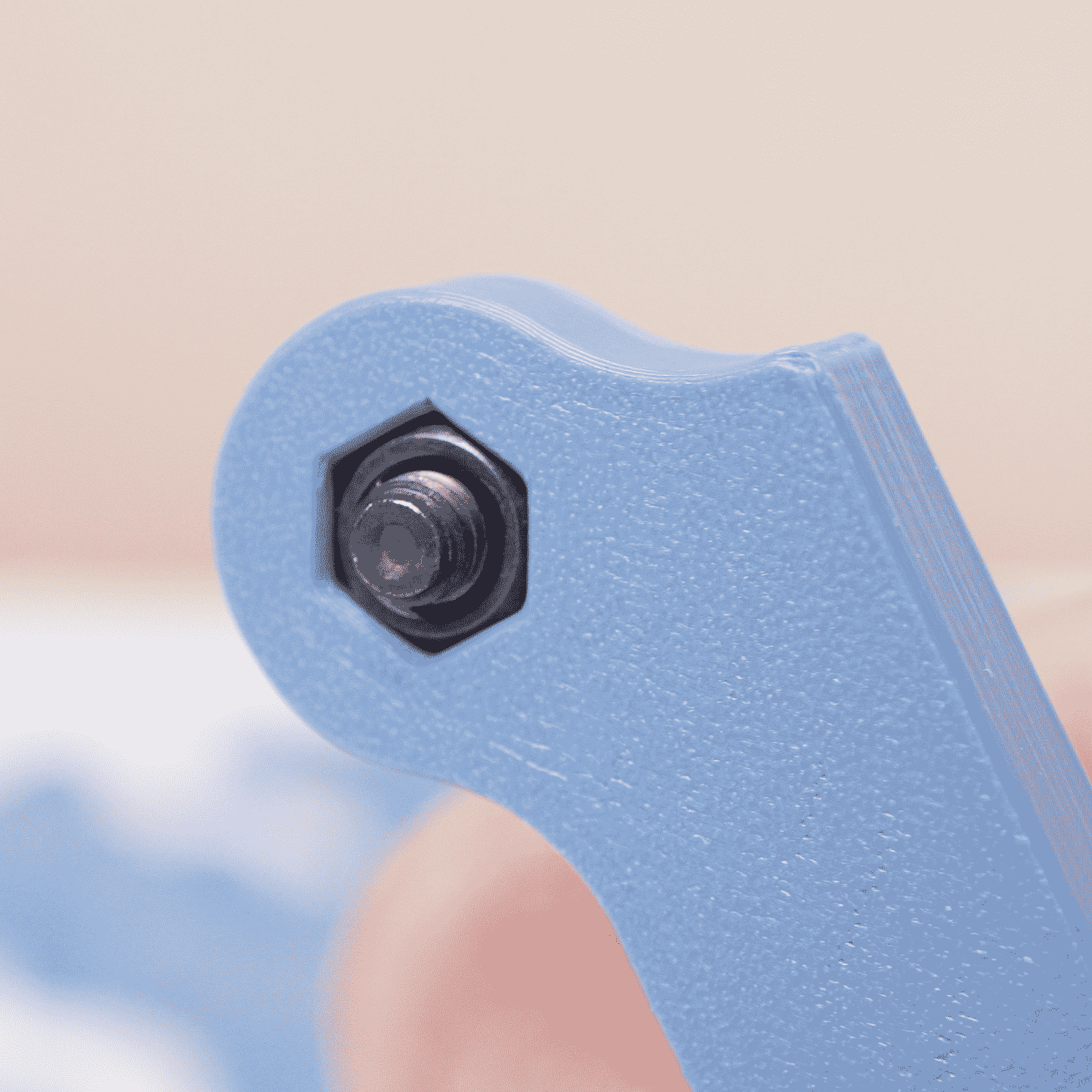
STEP 4
The nut should be pulled into place by the bolt from the opposite site
-
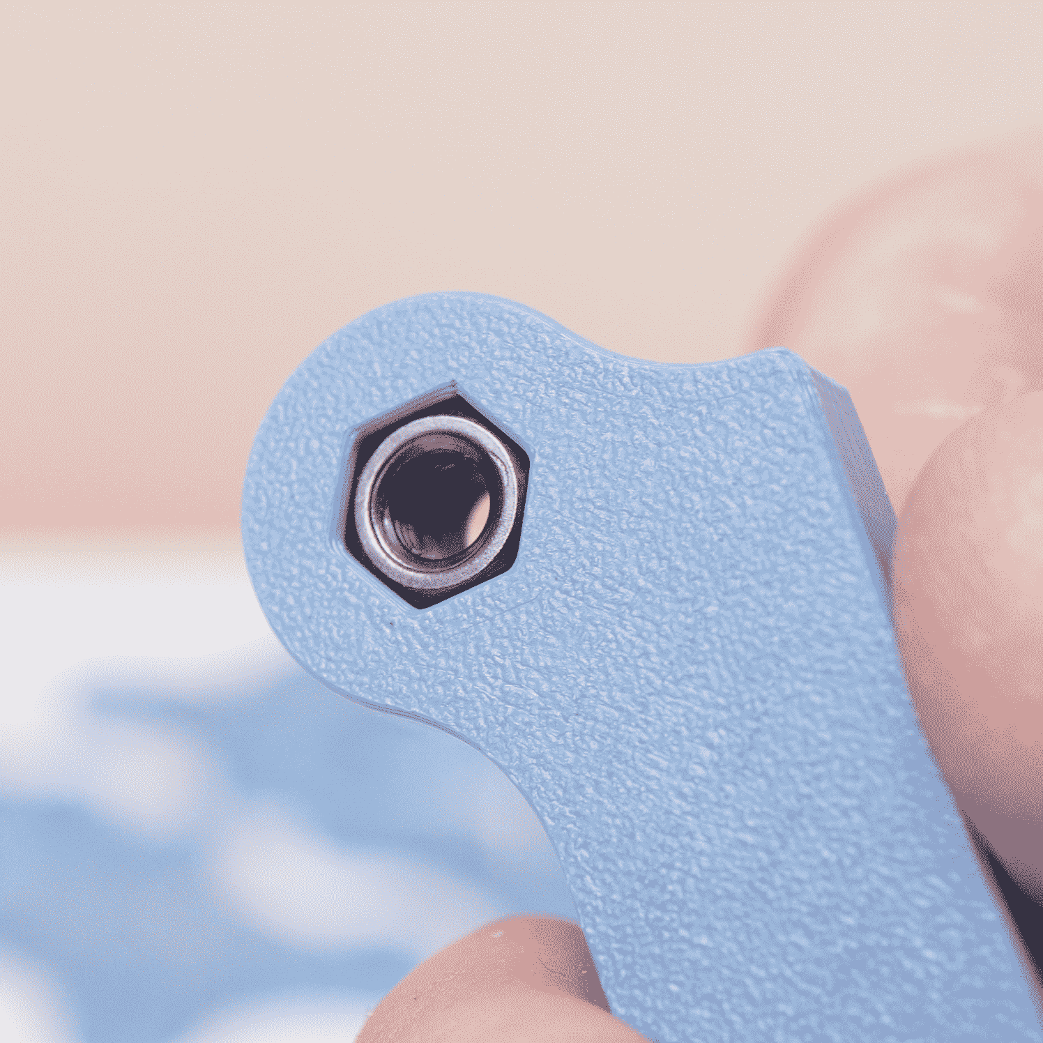
STEP 5
Remove the bolt from the piece and repeat if needed for other nuts


Collapsible content
ALTERNATIVE PARTS
Below are some of the alternative part options - review the prints below to see if you would like to make changes to the Standard Build.
Collapsible content
NAMEPLATE CUSTOMIZATION
NAMEPLATE FOR DELACK FOR A1 MINI

If you want to customize the nameplate on the front of your DELACK, there are a couple of options available to do that.
Option #1: EDIT STEP FILE
We have provided a STEP file in the DELACK A1 MINI - ALT PARTS project, so you can download and edit the file in your CAD software of choice. We recommend embossing the text to least 0.4mm. If you need to learn how to change colors with our without an AMS, follow the instructions below for the other methods.
Option #2: EDIT NAMEPLATE - PAUSE METHOD - NO AMS
If you DO NOT have an AMS Lite, you can use a print pause to change the filament so that you can create a nameplate with 2 colors. We have already added the pause on the 3rd layer of this plate, so all you need to do is change what the text says and print the file off, changing the filament when the print pauses.
Step 1: Click on the object on the EDIT NAMEPLATE (PAUSE - NO AMS) plate


Step 2: In the menu on the left, switch the toggle to Objects and then expand the dropdowns under Plate 1 and NAMEPLATE BLANK.stl and select editable_text

Step 3: Select the Text shape button in the top toolbar (the T with a lowercase a)

Step 4: Change Input text to whatever you prefer. You may need to adjust the Size and Text Gap some, but be careful not to make things too small since the printer will have trouble resolving small details. To recenter the text, move the text to the middle using the pink position control icon.


Step 5: Reslice the plate. Notice that there is a pause on the third layer (0.6mm) where the printer will pause and allow you to switch the filament to another color. If you just want to print the part in a single color, delete the pause before printing. That's it!

Option #3: EDIT NAMEPLATE - AMS FILAMENT CHANGE
If you DO have an AMS Lite, all you need to do is change the text on the file and select the color you would like for each part of the nameplate.
Step 1: Select the object on the EDIT NAMEPLATE (AMS) plate


Step 2: In the menu on the left, switch the toggle to Objects and then expand the dropdowns under Plate 1 and NAMEPLATE BLANK.stl and select editable_text

Step 3: Select the Text shape button in the top toolbar (the T with a lowercase a)

Step 4: Change Input text to whatever you prefer. You may need to adjust the Size and Text Gap some, but be careful not to make things too small since the printer will have trouble resolving small details. To recenter the text, move the text to the middle using the pink position control icon.


Step 5: Reslice the plate. Notice that there is a filament change on the third layer (0.6mm) where the AMS will switch the filament to another color. To assign the color, drag the vertical slice selector on the right to the third layer (0.60) and right click, select Change filament, and assign the filament based on your preference.


Option #4: BLANK INSERT
If you don't like any of these options, and you also don't like the standard "DELACK" nameplate, you can print off the BLANK NAMEPLATE and customize it manually with a marker/laser/etc (or leave it blank).

NO LED
NO LED

If you do not want to add the LED to the DELACK, you can print this plate which has 3 solid top supports (two for the sides and one for the back where the LED usually goes). If you already have the 2 sides printed, just print 1 of these pieces (the side and back pieces are the same). But who DOESN'T want an LED light!?

SHORT TANK
Short Tank

If you prefer to leave your A1 Mini filament in the stock location, we have created a shorter tank that allows you to offset the printer inside of the enclosure some so that there is extra space to change the filament using the stock filament holder.
HINGE ON LEFT
Hinge on Left

Hinge set for the left hand side - if you are looking at the enclosure, this is the set of hinges that will put the hinge near your left hand.
CABLE CHANNEL PIECES
Cable Channels

If you want to organize cables that are running along the inside of your printer, consider printing the supports with cable channels

RIBBED CORNER GUARDS
Ribbed Corner Guards

Change up the look of the corner guards by using this ribbed version

MAGNETIC FILAMENT GUIDE
Magnetic Filament Guide

If you want a simple guide for your filament using the stock A1 Mini filament holder, print this piece off and insert 2 magnetics into the cavities.

DELACK A1 MINI ASSEMBLY GUIDE
Collapsible content
#1 - Riser and Tank Assembly
DELACK for A1 Mini Assembly Guide
#1 - Riser and Tank Assembly

Step #1: Print Off Plates #1 - #4
From the print files, make sure you have the first 4 prints completed:
1 - FEET + TOP CORNERS + SIDE CORNERS
2 - SKIRT (with or without AMS depending on your setup)
3 - TANK
4 - CLIPS
Step #2: Add Rubber Feet
Find the 4 Feet prints and add the rubber plugs to the bottom of all 4 pieces - make sure the flat part of the blue is oriented down as the foot


Step #3: Add the Corner Riser Side Pieces
Find the 8 riser pieces that are the same length (these pieces are the middle length ones - not the shortest or the longest) and insert them into each corner piece using the clips


Step #4: Add the Front and Back Riser Pieces
Find the 2 longest skirt pieces - the one with the gap goes in the back for the power cable to pass through and the solid one goes in the front

Step #5: Finish the Right Wall
Find the 2 smallest pieces that are not used for the tank - they will either be solid (for non-AMS builds) or have a small gap (for AMS builds so that the AMS cable can reach the printer) - add these pieces to the right side
No AMS Version


With AMS


Step #6: Assemble Tank Guide
In the last gap on the riser, add the tank guide pieces - BE CAREFUL AS THESE CAN ONLY GO ON ONE WAY (SEE IMAGES)


Now, add the rail guide piece on top - this should fit flush on the inside if you did the previous step correctly with a small gap on the outside


Step #7: Complete the Tank
Add the friction fit oval slot and clip to the two halves of the tank to finish assembly - the tank should fit flush with the walls

Step 8: Add the Nuts to the Feet
Finish off the Riser by adding x2 nuts to all of the feet


Riser is done!
#2 - Wall Assembly
DELACK for A1 Mini Assembly Guide
#2 - Wall Assembly

Step #1: Print Off Plates #5 - #8
From the print files, make sure you have the following prints completed:
5 - LED + SIDE TOP PLATES
6 - FRONT SUPPORT + BACK COVER
7 - NAMEPLATE
8 - FAN COVER
Step #2: Add Top Corner and Middle Corner Pieces
Find the x4 Top Corner and x4 Middle Corner pieces to create the walls of the enclosure - make sure that the middle side holes are at the top of the side pieces


Step #3: Add the Front Top Support Piece
Assemble the Nameplate with the Top Support Piece


Add the piece to the front of the enclosure above the door frame

Step #4: Add the Side Top Middle Pieces
Add the two Top Middle support pieces

Step #5: Add the Back Bottom Wire Cover
Add the cover for the bottom wire gap to the back bottom of the enclosure


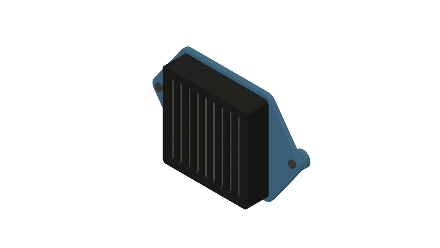
Step #6: Add the Fan Cover
If you don't plan to add a fan to your DELACK, you can add the fan cover now - make sure you use the Nut Spacer parts which are on the same build plate as the fan cover


Done with the walls!
#3 - Join Riser and Walls
DELACK for A1 Mini Assembly Guide
#3 - Join Riser & Walls

Step #1: Check for x8 Nuts the Enclosure on the Riser
Double check the nuts are inserted into the corner riser on all 4 corners

Step #2: Lower Enclosure onto Riser
Gently lower the walls of the enclosure on top of the riser

Step #3: Add 8 Bolts
Use x8 bolts to secure the Riser at the corners

Done with the Riser!
#4 - LED Assembly
DELACK for A1 Mini Assembly Guide
#4 - LED Assembly

ASSEMBLY VIDEO
This video is based on a previous design where mounting the rear mount to the top plexiglass was not part of the design (Step 12) - we now recommend using the top mounting technique since it allows you to remove the top panel WITH the LED Light. The other techniques shared in the video are still useful if you are having issues with assembly. The main assembly video also goes through the LED assembly at a faster pace.
CLICK HERE TO VIEW THE ASSEMBLY VIDEO
Step #1: Print Off Plates #11 - #14
From the print files, make sure you have the following prints completed:
11 - LED LIGHT 1
12 - LED LIGHT 2
13 - LED LIGHT 3
14 - LED LIGHT 4
Step #2: Insert the LED Light Strip into the Rear LED Mount


Place the cable attached to the LED strip into the cable channel (1) as you begin to rotate the switch into position (2).; as you rotate the switch into place, make sure that the cable coming out of the enclosure is going i the bottom cable channel (3)

Once the cables are in position, push this side all the way into place - you may need to gently pull on the cables entering and exiting the part to get it perfectly into position

Now, the LED switch should be fully installed

Step #3: Layout the Smaller LED Insert Parts
Layout the parts as shown below
Step #4: Layout the LED Parts
Place the LED Light with Rear Mount onto into place and feed the LED Light Strip through the channel (following the path of the arrows)
Step #5: Add LED Cover Parts
Add the LED Cover pieces shown below - there are slots that must align to fit properly


Step #6: Add the Remaining LED Cover Parts
Place the remaining covers into position
Step #7: Add the Remaining LED Cover Parts
Insert the 2 nuts into the slots - make sure they are pushed all the way to the bottom of the hole
Step #8: Add Nuts to the Rear Mounting Piece (OPTIONAL)
If you would like to anchor your LED Enclosure to the back wall of the enclosure, add 2 nuts to the back piece as shown***This will require you to remove these bolts prior to removing the top which reduces accessibility. We generally recommend skipping this step unless you are confident that you will not need to remove the top of the enclosure.***

Step #9: Add the Top Plexiglass
Place the top plexiglass piece beneath the LED light and align the holes
Step #10: Slide to Edge of Table
Carefully slide the plexiglass to the edge of the table so that you can attach the LED Light - you may want to temporarily add something heavy like a spare filament roll to the end still on the table
Step #11: Slide to Edge of Table
Using the Hole Filler pieces and a bolt, attach the LED Light to the top plexiglass piece
 Step #12: Add the Top Bolt
Carefully flip the plexiglass and LED light over and add the top bolt - this step is not shown in the video as this is a newer design, but we recommend using this method rather than mounting via the 2 back bolts so that the LED Light can easily be removed WITH the top panel
THIS IS A SELF-THREADING BOLT, SO YOU WILL NEED TO USE SOME FORCE TO GET THE THREAD STARTED

Done!
#5 - Door Assembly
Wall Assembly
Now, we can assemble the walls of the enclosure. Add the BACK plexiglass panel to one of the SIDE plexiglass panels first.

Next, add the other SIDE plexiglass panel.

Now, add the DOOR FRAME to the front of the enclosure.

Getting closer!
#6 - Final Touches
DELACK for A1 Mini Assembly Guide
#6 - Final Touches

Step #1: Add Rubber Plugs as Needed
Use the included rubber plugs to fill any holes on the back of the enclosure that you do not need

Step #2: Add the DELACK to the A1
Once your printer is in position, add the enclosure around the printer. Be careful not to hit the Filament Tank Guide as you place the enclosure around the printer. Alternatively, you can place the printer into the enclosure if that's easier for you.


Step #3: Add the Tank
Add the Filament Tank now that everything is in posiiton

Step #4: Add Plugs to the Top Plexiglass
Add the x2 rubber plugs to the top plexiglass panel - do not add the rightmost plug yet (see Step 5)

Step #5A: Reroute the Filament (NO AMS LITE)
Please skip to Step 5B if you have an AMS Lite
We have 3 options for filament routing:
- Use default positioning (not recommended) - the positioning of the filament is not meant for an enclosure - if you do want to keep this filament position, we recommend printing the Short Tank Alt Print so that you have more room to change the filament
- Use the Filament Clip (okay but not optimal) - we created a simple Magnetic Filament Guide Alt Print so you could use the filament holder as a guide for your filament if you'd like a simple solution to guide your filament
- Modify Filament Path (recommended) - Our recommendation is putting a small hole into one of the plugs and then re-routing the filament tube to the top panel - there is a small piece printed as part of Print #9 that finishes off the setup nicely as a rubber plug cover


Step #5B: Reroute Filament (AMS LITE)
Please skip to Step 6 if you have already completed this step
Insert the quadruple filament tube sleeve into the hole shown above (rather than using a rubber plug) and then add the filament tubes one at a time
This will fit tight but once its in place, it works well - just make sure you pull enough slack out of the filament tubes and that you put the AMS close to the enclosure (consider printing the AMS Lite Stand that we developed that was made specifically for this)


 Step #6: Add Rear LED Bolts (Optional)
If you would like extra rigidity, you can add these bolts to the back but this will limit how easily you can remove the top of the enclosure to access your printer (LED Switch not shown)

Step #7: Add Top Corner Covers (Optional)
We DO recommend adding these corner covers - they complete the look as well as add protection from the sharp plexiglass corners (Print #15 - OPTIONAL GUARDS)

Step #8: Print!
That's all folks!

PS: We've created a lot of various Accessory Prints, so be sure to check those out. If you enjoyed the build and instructions, it would REALLY help us out if you would consider leaving a review on Amazon for us!
Click Here to Leave a Review on Amazon - THANK YOU
Thanks again for being our customer,
Joseph - Founder of 3D Sourcerer
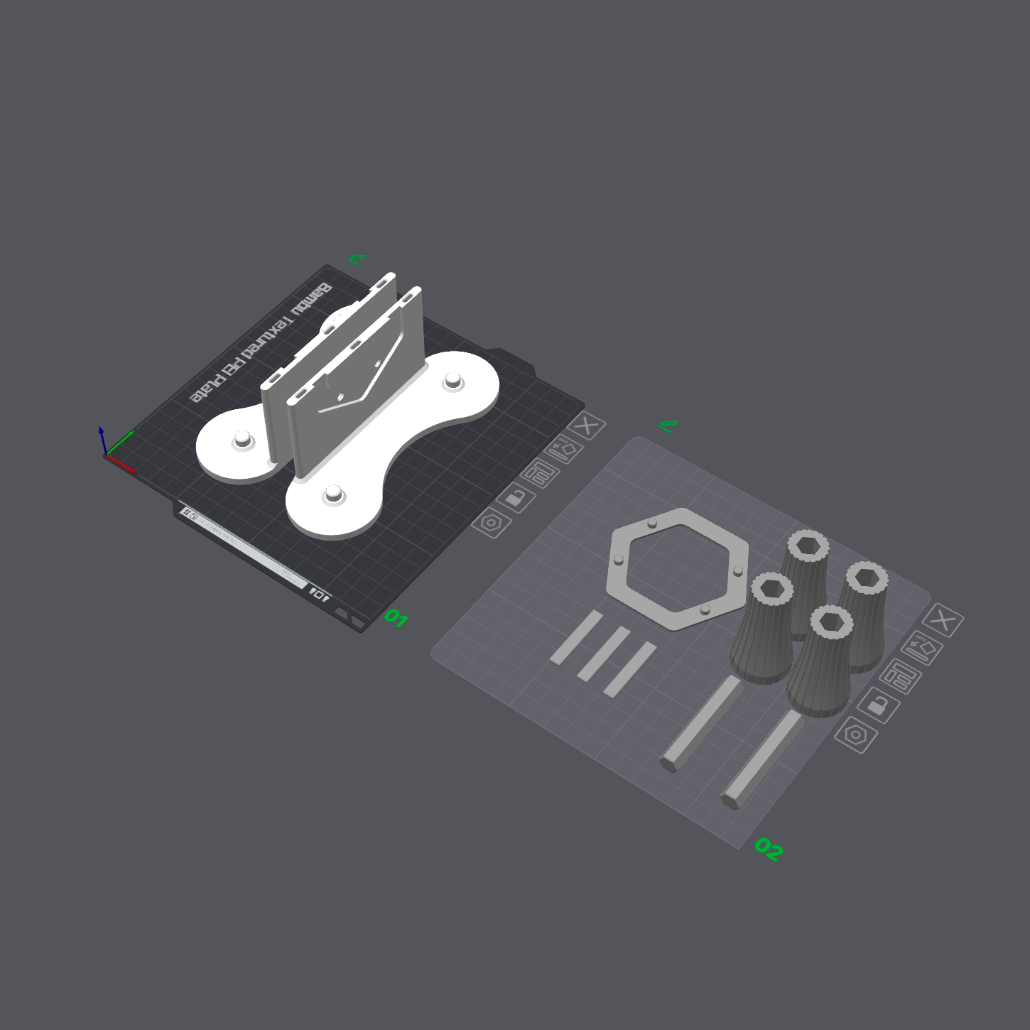
#7 - Universal Filament Holder Assembly
SELF-CENTERING FILAMENT HOLDER ASSEMBLY GUIDE

CLICK HERE TO DOWNLOAD FILES ON MAKERWORLD
CLICK HERE TO DOWNLOAD FILES ON PRINTABLES
PARTS REQUIRED
x4 608 bearings (included in DELACK/SUMO/UNIVERSAL 3D Printer Enclosure kits)

CLICK HERE TO PURCHASE SUPPORTED BEARINGS ($5)

We added some grooves to add friction so that the roller would spin with the filament spool.

There's a hex rod that connects the two bodies together in the middle, which allows you to print these pieces in the optimal orientation.


Please print in the orientation shown below for the best results.

Add the 3 inserts to reinforce the filament roller.

The two sides have interlocking features, so the easiest way to assemble them is to add both rollers to one side first. Make sure the bearings are in place.

Add the other side and ensure all pieces are aligned correctly.

Add the interlocking hex piece in the center. The hex fits snugly, so you may need to apply some force.

Now you are ready to roll!
#8 - AMS Lite Stand Assembly
Print #6 Assembly
Latch Set
The most important part of LATCH assembly is to make sure that the magnets are attracting each other. The magnets should fit snugly into the magnet hole, but you may need to use the side of your pliers to press the magnets into place.

A tip for inserting the magnets is to use the side of the needle nose pliers as shown below to press the magnets into place. It is a tight fit (to prevent the magnets from getting pulled out when you open the door), so you should expect to press pretty firmly.


After making sure that the magnets are attracting each other, add the LATCH set with the cutout in the design to the DELACK DOOR FRAME as shown below.

Next, add the LATCH to the DOOR. Double-check that the magnets attract each other before placing them.

Now, the DELACK is almost finished!

TONS OF MODS
DELACK ACCESSORY PRINTS
With a wide range of accessory prints, there's a print for just about any printing setup!
LIGHT UP YOUR PRINTER
LED LIGHT
We included an LED light with the DELACK Enclosure for a reason! Follow this Assembly Guide to install the LED Light accessory.